


1.1 Application and scope
This machine is used for sequential work of PET bottle filling and capping.
This machine is mainly used for normal temperature filling of liquid products such as mineral water, CSD etc.
2. main structure and working principle
2.1.1 Rack and protective doors
This part is the support and safety guard of the whole machine. The material of the rack is stainless steel, while the protective doors around are organic glass.
2.1.2 Transmission system
This system includes motors, reduction gearboxes, star axles, cap screwing spindles, filling capping system slewing, etc.
2.1.3 Filling system
This system includes filling tank, filling valves, liquid level control devices, and its subsidiary bodies etc.
2.1.4 Bottle conveying system
This system includes bottle feeding star wheel, bottle collecting star wheels, middle star wheel, bottle retaining plate, bottle protective bar plates, etc.
2.1.5 Control system
This system mainly includes electrical cabinet, PLC control systems.
2.2 Working principle
The bottle blowing system produces the qualified bottles for filling. Then the star wheel transmits the bottles to the filling system and locates them on the bottle locking board. With the function of cam and bottles, the filling valve realizes the filling process of open, filling and close by its spring (no bottle no filling). Next, the middle star wheel will take out the filled bottles and transmit them to the capping system. The magnetic capping head will screw tight the bottles with caps. Finally, the bottle collecting star wheel will take out the bottles and send them to the transmission system for following operation.
2.3 Main structure
2.3.1 Driving process
The main drive motor of the machine is a 4KW variable frequency motor. The main motor drags the worm reducer through vee belt. One of the shaft gears meshes with the large slewing bearing, which will mesh with the mid gear. This drives the capping gear and bottle collecting star wheel turn. All these movements achieve the whole driving process of bottles feeding – filling – capping – bottles collecting.
2.3.2 Filling system
The entire filling system component is installed on the transmission plate of the rack, under which there is a large slewing bearing. The variable frequency motor drives the whole filling system through reducer and main gear.
picture 2.3.2.1
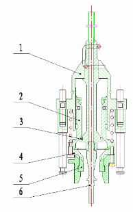
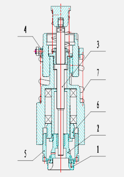
(1) Filling valve ( picture 2.3.2. 1)
This is a built-in filling valve, consisting of jacket, valve core, valve, base, spring, etc.
(a)When bottles are clamped to the bottle locking board by middle star wheel, they are jacked up by cylinder. With the function of cam, the bottles rise with gasket 5 on bottle neck, together with orientating block, valve head 4 and guide bush 2.
(b)The liquid material in the filling tank flows into the bottle through valve head 4. Meanwhile, the existing air inside the bottle flows into the tank through vent-pipe.
(c)The liquid material will stop flowing when the liquid level reaches the nozzle of vent-pipe 6, because the exhaust channel is blocked at that time. The liquid level can be changed by changing the length of vent-pipe. Then the cylinder brings down the bottles and sends them to the middle star wheel, which will send the bottles into the capping machine.
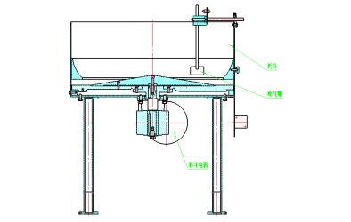
(2) Filling tank
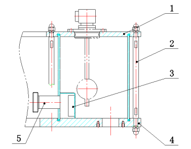
(1) The filling tank is made with stainless steel, with solid and reliable structure. It complies with the food hygiene requirements. There is a baffle plate and locking device on the tank.
There are four baffle plates installed in the liquid feeding mouth. They are used to bring down the influence to liquid surface when filling. They are helpful for smooth liquid surface and stable filling.
1. Cover
2. Draw bar
3. Baffle plate
4. Tank bottom
5. Liquid feedingTube
(1) Liquid level control devices (picture 2.3.2.2)
If the liquid level in filling tank is unstable during filling, the foaming or filling volume shortage problem may occur. Therefore, it’s necessary to set a liquid level control device to keep the liquid level stable inside the tank.
There’s liquid-in valve in the inlet of liquid pipes, and the liquid level in the filling tank would be monitored by the liquid level sensor.
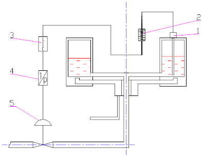
1. Liquid level sensor
2. Mercury swivel joint
3. Liquid digital meter
4. Electrical valve positioner
5.Liquid-in valve (Eccentricity-adjusting rotary valve )
Liquid level control devices (picture 2.3.2.2)
Liquid level sensor (1) can recognize the liquid level and change to electric signal, then pass from the mercury swivel joint (2) to liquid digital meter (3),and then adjust the liquid inlet valves (5) via electrical valve positioner (4), which can finally control the liquid level. You can manually set the liquid level in the filling tank on liquid digital meter and you can reset the value while the filling machine is running.
(4) Filling tank cleaning liquid emptying solution (picture 2.3.2. 3)
We equip CIP Cleaning Cup for each filling machine. After cleaning, it needs to remove cleaning cup as the following picture to discharge the residual fluid in the tank.
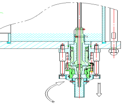
Emptying of the tank (picture 2.3.2. 3)
2.3.3 Capping systems
Capping system is mainly consist of capping heads, cams, hollow axels, sliding seats, cap pick-up plate, cap transmission channels, hoppers and other parts.
The caps would be collected from the hopper and cap distributor, with cap channels, the caps are transferred to the cap pick-up plate which would send the caps to the place under the capping heads. After fetching the caps, the capping heads would set the caps above the necks, and get the caps pressed and screwed with the function of cams and internal gears.
(1)Capping Head (picture 2.3.3.1)
Capping head consists of ferrule, chuck, internal and external magnetic coils, springs, bearings& etc.
For the same bottle type and cap, there’s no need to adjust the capping heads after commissioning. But please make sure the ferrules (Part 1) would not get stuck by any foreign matter or the edge of chucks (Part 2) would not get damage, and furthermore, do not make failure on caps fetching and screwing due to missing of shield rings.
 Capping head (picture 2.3.3.1)
The working method of the capping is as below: the ferrule fetches caps through cap pick-up plate, with the function of cams curves, the caps would be pressed into chuck, and they’re next progressed on the necks which are positioned by the neck’s support ring and its track. At the point of lowest of cam curves, the torque exceeds the magnetic torque by the internal and external magnetic coils so that the capping head is leaving the neck with lift of scroll wheels and get screwing done, where caps would not break owing that the external ring of capping head rotates in the meantime.
The ejector pin (Part 3) is to push the remaining caps as sometimes it happens at the very beginning that less bottles go into the line so caps are superfluous.
The way to adjust the capping heads: The capping heads need adjustments when caps change. On the above process, springs (Part 7) controls the positive pressure of the torque, and could decrease and increase the positive pressure by positioning the screws (Part 4). And the internal magnetic coil (Part 5) and external magnetic coil (Part 6) controls the screwing torque, while internal magnetic coil is stationary, and make the external magnetic coil up and down by loosening the fastened screws to bring up and down the screwing torque. And thus, the screws are to be fastened after the adjustment so that the screwing torque is consistent.
(2) Cap pick-up Plate and Cap Transmission Channels
Cap pick up plate composed mainly of lift shafts, cap distributing plate, whose role is to send the caps in the channels to ferrule. And therefore the gap between the caps and ferrule is quite important.
There’re two ways to adjust the gap. One is to increase and decrease quantity of brace rods’ spacers synchronously, and the other is to loosen the top screws and turn the shield ring so that the total height changes.
The cap transmission channels includes the sliding plates, cylinder for stopping caps, proximity switch, blowing pipes & etc. The cylinder for stopping caps works mainly according to the bottle-in checking signal while the proximity switch controls the movement of distributing motors (start or off) by shortage or overfilling of caps.
(3) Hopper (picture 2.3.3.2)
The hopper consists of cap-distributing plate, cap-feeding plate, cap-feeding box, motors & etc.
The hopper motor motivates the round plate to drive the caps, with the help of blowing nozzles, the caps go into the caps outlet with cap-distributor. Only caps with mouth upward can pass the cap-distributor and enter the sliding channels, while those with mouth downward would go through the return cap channels back to the hopper. This approaching is suitable for the caps whose diameter is bigger than the height, however not all caps under this condition would agree to this solution for distribution.
If some caps with mouth downward could enter the sliding channels, then you need to slightly reduce the distance between the cap-distributing plate and the cap-feeding plate. To realize this, you need to disassemble the cap-feeding plate, and unscrew the bolts in the push plate, then get the distance-fixed plate and cap-distributing plate off the hopper, then next is to dismantle the one spacer in each distance-fixed plate. Finally follow the reverse process to assemble the hopper. Of course it might need to remove not only one spacer in each distance-fixed plate, it should depend on the degree of wear. When the adjustment is not sufficient, some caps might be squeezed in the gap and get distortion. But when some damaged caps are found, firstly check if caps are originally bad when sourcing, rather than adjust the hopper at once.
The rotational speed of cap-distributing plate could be adjusted by stepless variable transmission. If the cap-feeding speed could satisfy the screwing capacity, the rotational speed is suggest to adjust as low as it can, as this could reduce caps stirring to avoid damage. Some models would be equipped with fixed speed reducer, the rotational speed need no adjustment in this case. The gas nozzle adopts compressed air to get the caps move into the cap transmission channels quickly, and the pressure of the nozzle could be adjusted by pressure-regulating valve.
Hopper (picture 2.3.3.2)