


· This machine has a compact structure, a perfect control system, easy operation and a high degree of automation.
· All parts in contact with the material are made of imported high-quality stainless steel, with no process dead corners and easy to clean.
· It adopts high-precision, high-speed quantitative filling valve, accurate liquid level and no liquid loss, ensuring excellent filling quality.
· The capping head adopts a constant torque device to ensure the capping quality.
· It adopts an efficient cap sorting system with perfect cap feeding technology and protection devices.
· Changing the bottle shape does not require adjusting the height of the equipment, and can be achieved by replacing the bottle star wheel, which is simple and convenient to operate.
· The filling system adopts bottle neck feeding technology to avoid secondary contamination of the bottle mouth.
· It is equipped with a perfect overload protection device, which can effectively protect the safety of the machine and the operator.
· The control system has functions such as automatic water level control, cap missing detection, bottle flushing automatic stop and output counting.
· The bottle washing system adopts a high-efficiency cleaning spray nozzle produced by the American spray company, which can clean every part of the bottle.
· The main electrical components, electric control valves, frequency converters, etc. are all imported to ensure the excellent performance of the whole machine.
· All components of the gas system are internationally renowned products.
· The whole machine operation adopts advanced touch screen control, which can realize human-machine dialogue.
CGF24-24-8 PET bottle pure water washing, filling and capping machine has absorbed the advanced technology of similar foreign products, with stable performance, safety and reliability. This machine has a compact structure, perfect control system, convenient operation and high degree of automation;
The air conveying channel and the bottle feeding dial wheel direct connection technology are adopted, and the bottle feeding screw and conveyor chain are eliminated, making it simple and easy to change the bottle type. After the bottle enters the machine through the air conveying channel, it is directly sent to the filling part by the bottle feeding steel dial wheel (neck clamping method). This machine has a compact structure, perfect control system, convenient operation and high degree of automation;
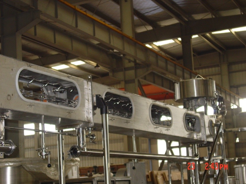
1.1 Aseptic water bottle washing
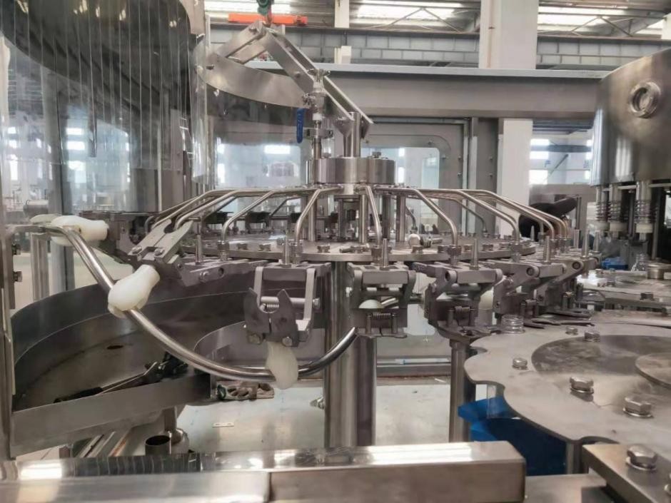
After the bottle enters the main machine, it enters the bottle washing machine through the transmission star wheel. The bottle clamp clamps the bottle mouth and turns it upward 180° along the bottle washing guide rail to make the bottle mouth face downward. In the specific area of the rinser (determined by the water distribution plate - the rinse water is pumped into the water distribution plate by the rinse water pump, and then distributed to the rinse clamp through 24 pipes), the rinse clamp nozzle sprays sterile water to rinse the inner wall of the bottle. After rinsing and draining, the bottle is clamped by the bottle clamp and then turned down along the guide rail 180°, so that the bottle mouth is facing up. The washed bottle is guided out of the rinser through the transition steel dial (pure water rinse bottle) and transmitted to the next process - filling.
1.2 Filling
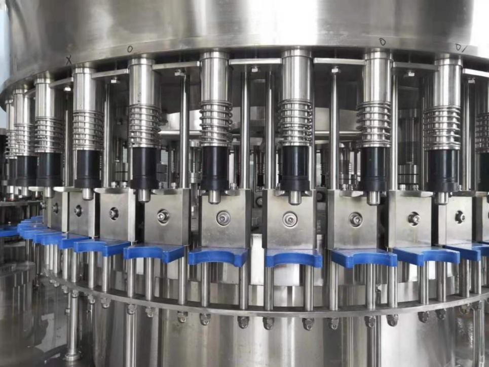
During filling, the bottle is lifted by a cylinder, and the high-speed operation is stable and reliable. Compressed air is connected to the lifting cylinder through the air inlet distributor. During operation, the compressed air is injected into the cylinder A chamber through the air injection pipe, so that the cylinder rises upward. After the bottle mouth rises, the filling valve is pushed open and filling begins. When the filling set liquid level is reached, the filling valve return port is blocked by the material, and the filling is completed. Then the cylinder descends under the action of pulling down the cam, and the gas in the B chamber is discharged through the exhaust screw.
1.3 Capping
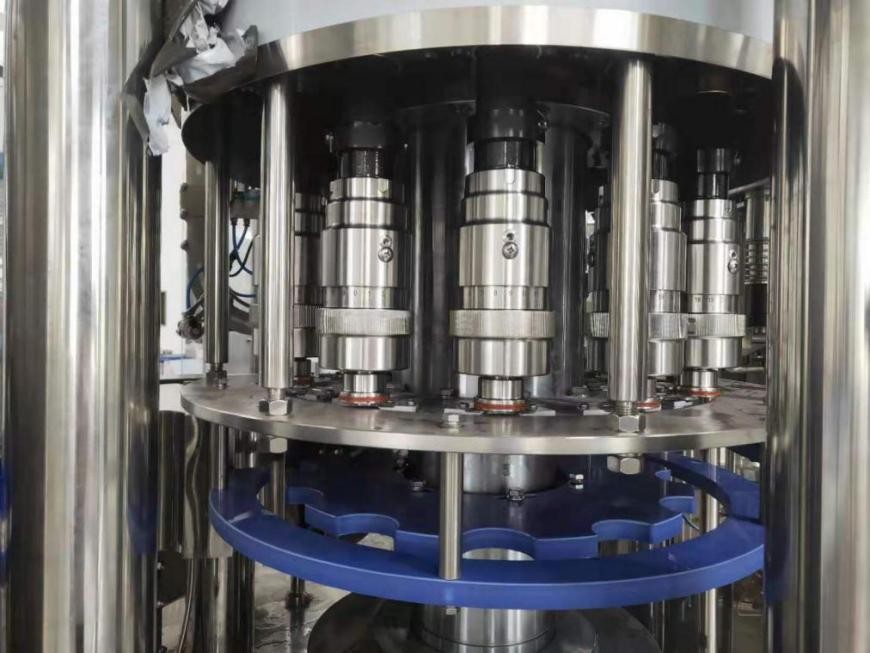
After filling, the bottle enters the capping machine through the transmission star wheel. The anti-rotation knife on the capping machine clamps the bottleneck part, and together with the bottleneck guard plate outside the capping machine, the bottle is kept upright and prevented from rotating. The capping head revolves and rotates under the drive of the capping machine main shaft, and realizes the actions of grabbing, covering, screwing and removing the cap under the action of the cam to complete the entire capping process.
The capping head adopts a magnetic constant torque device. When the capping head takes the cap through the capping plate, the top cap sleeve holds the cap and straightens the cap to ensure that the cap is in the correct position in the capping mold and ensure the capping quality. When the capping is completed, the capping head overcomes the magnetic force and slips, and the bottle cap will not be damaged. At the same time, when the capping head rises, the top cap rod pushes the cap out of the capping mold.
The capping plate transmits power to the capping head through the pin wheel to ensure that its movement is synchronized with the capping machine. The bottle cap enters the capping plate through the capping channel, and then the bottle cap transmission star wheel separates the bottle cap according to the work station and transmits it to the capping head to take the cap.
1.4 Technical description of automatic capping machine
Working principle:
· A detection switch is installed on the capping machine. When the bottle caps are consumed to a certain extent, the detection switch sends a signal to start the capping machine to deliver the caps.
· A certain number of bottle caps are loaded in the cap bin. The vibration plate shakes the bottle caps into the air duct under the action of the vibration motor. Under the action of the wind of the fan, the bottle caps are delivered to the capping machine through the conveying air duct.
Technical parameters:
(1) Model: SG-Ⅱ
(2) Fan: 380V, 0.55KW
(3) Vibration motor: 380 V, 60W
1.5 Online cleaning and disinfection of bottle caps
1) Equipment overview
· The bottle cap disinfection machine is installed outside the sterile room. The bottle caps are arranged by the capping machine and then enter the bottle cap disinfection machine. They are rinsed with disinfectant and sterile water respectively, and then sent to the capping machine through the cage.
2) Main features
· High-efficiency centrifugal cap sorting method, with small cap wear.
· A bottle cap detection mechanism is provided, and the cap signal is used to control the start and stop of the bottle cap lifting machine.
· The empty caps are sprayed with online continuous disinfectant on the conveying and disinfection rails. The angle design of the nozzle ensures that the disinfectant is sprayed to each point inside the cap. Afterwards, the sterilized empty caps are sprayed and rinsed with sterile water.
· The processing time is ≥20s.
The disinfectant storage tank has high and low liquid level detection and automatic disinfectant replenishment functions.
1.6 Conveying
1) Full bottle conveying
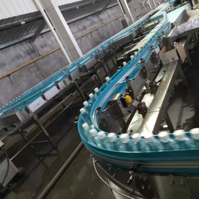
The conveyor line is a bridge connecting various production equipment, which directly affects the efficiency of the production line. In the configuration of the conveyor line, it must be considered that when the rear equipment is temporarily stopped (for example: changing auxiliary materials, etc.), it will not affect the operation of the front equipment. At the same time, the front and rear equipment should be well connected together to enable the entire production line to achieve a higher operating efficiency. The mechanical structure of our company's conveyor line is a new design, and the connecting components are all formed by stamping or bending, which has the advantages of good rigidity, light weight and good interchangeability.
2) Empty Bottle Conveying
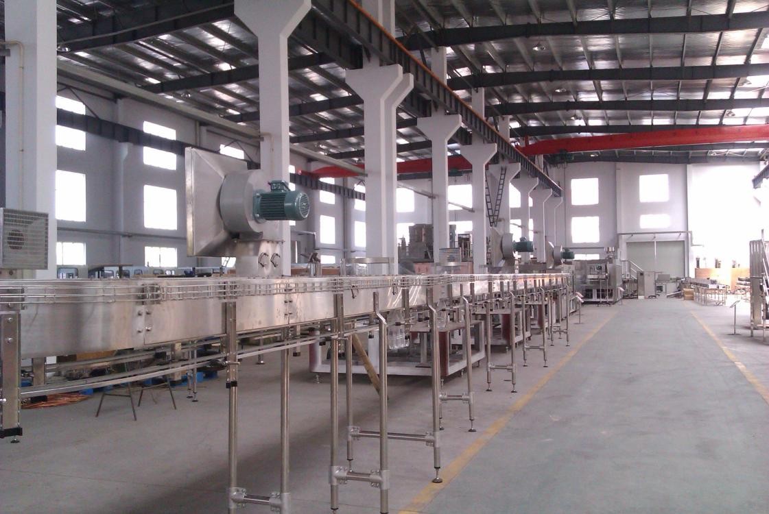
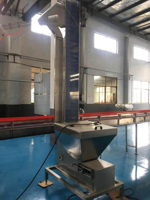
1. Overview of Air Conveying Channel
(1) Equipment Overview
· The air conveying channel is supported on the ground by a tripod, and the fan is installed on the upper part of the air conveying channel. Each fan is equipped with an air filter at the air inlet to prevent dust from being blown into the bottle. The bottle neck is clamped by the bottle hanging plate in the air conveying channel and is transported to the bottle rinser by wind.
(2) Main Features
· Except for the plastic and nylon parts such as the support legs and bottle hanging plate, the rest are made of high-quality stainless steel.
· The air inlet of the fan outside the clean room is equipped with a primary air filter to prevent dust from being blown into the bottle.
· An automatic bottle dropping device is provided on the air conveying channel, which is driven by a cylinder. When the rear main engine stops temporarily or slows down, the empty bottles on the air conveying channel reach a certain number, and the bottles blown out by the bottle blowing machine can be removed from this mechanism and collected, and then the automatic bottle dropping device can be opened manually and the bottles can be manually hung on the air conveying channel. This ensures that the blow molding machine does not need to be shut down in this case.
· Multiple groups of photoelectric switches are installed on the entire air delivery duct. The photoelectric switches near the cross duct are used to control the reversing of the cross duct. The other photoelectric switches installed on the air delivery duct are used to control the action of the automatic bottle dropping device installed on the duct, and control the smooth operation of the entire air delivery duct.
· A certain number of pneumatic bottle blocking mechanisms are installed at the cross duct, and the air delivery duct is controlled by the photoelectric switches.
(3) Technical parameters
· Duct length: Determined according to the layout diagram.
· Duct material: hanging bottleneck type conveyor, material is SUS304 polished panel, thickness 2mm
· Bracket material: 304 stainless steel, double legs
· Bottle neck guide material: free replacement if damaged within the one-year warranty period (6000 hours);
· Cable duct and cover: duct top side, stainless steel
Light inspection box
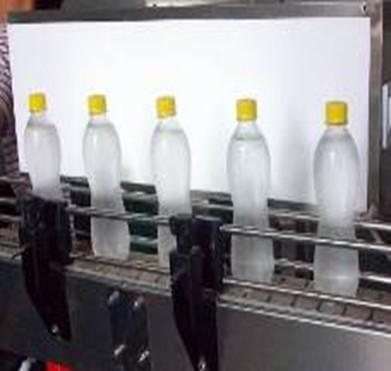
Description of the lamp used: in accordance with the national standard GB7000.10-1999, passed the national mandatory 3C certification
Performance characteristics:
a. Low power consumption and good brightness.
b. It can be started at low voltage 180V and will not burn out at high voltage 260V.
c. The high-frequency ignition lamp tube has bright and soft light and protects eyesight.
d. Durable, the average trouble-free working time is not less than 5000 hours.
e. High power factor.
f. Lamp model: T4-20W.
g. Rated power: 20W. 8. Power factor: >0.65.