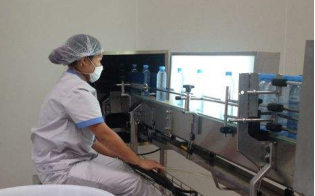
(I) HSTGZP4-4-1 Linear Filling Machine
Reference Diagram of Filling Machine Appearance
1. Product Overview
The RFC series is a new type of unit independently developed after years of upgrading and iteration, repeatedly absorbing customer feedback and learning from advanced foreign technologies. It mainly consists of 6 working components:
| (1) Inlet and Outlet Bottle Conveyor Belt | (2) Internal Washing Section | (3) Filling Section |
|---|---|---|
| (4) Waterfall Type Cap Feeder | (5) Cap Washing and Hanging Section | (6) Capping and Sealing Section |
2. Production Material Configuration
(1) The main frame is entirely made of food-grade 304 stainless steel. All bearing seats (25MM) and column square tubes (80X80) are national standard 304 stainless steel.(2) Material of outer frame decoration: 2.5mm stainless steel plate bent into shape, with 8mm tempered glass doors and windows.(3) Bottle mouth clamping device: Made of 6.0mm thick 304# stainless steel plate by laser cutting.(4) Adjusting device: Aluminum alloy slide rail.
3. Internal Washing Section
The 4 bottle mouth clamping manipulators are laser-cut parts of 304 stainless steel. They can be applied to various bottle types with the same bottle mouth without replacing accessories. The manual adjustment device is convenient and fast, and the stability is stronger than previous manipulators. The stainless steel power conveyor belt and motor-driven bottle washing operation are more stable and durable. The extended nozzle can directly penetrate into the bottle mouth, and under the action of injection pressure, it sprays water mist inside the bottle for more comprehensive internal cleaning, eliminating cleaning dead corners for both square and round bottles.
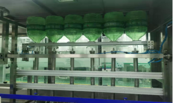
Reference Diagram of Internal Washing Section
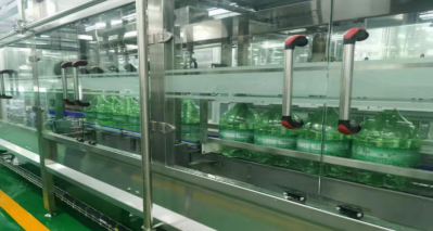
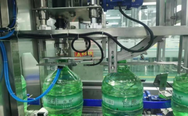
4. Filling Machine
(1) Adopts 304# sanitary pneumatic filling valves, with frequency converter three-speed filling for precise filling volume and no water overflow.(2) Uses 304# sanitary diaphragm valves for manual fine-tuning of water balance.(3) The filling volume for large and small bottles can be switched with one key on the touch screen.(4) The bottle mouth positioning for filling is processed by laser cutting of 6.0mm thick 304# stainless steel plate.
Reference Diagram of Filling Section
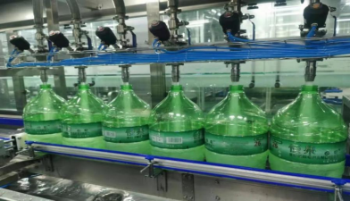
5. Capping and Sealing Section
All transmission parts are numerically controlled, and the capping shaft is straightened by grinding.The magnetic capping head and all accessories are numerically controlled.The bottle clamping plate has a stainless steel base inlaid with white steel blades, featuring long service life and easy replacement.The main shaft is equipped with a stainless steel sleeve for rust prevention and straightening.Adopts magnetic capping structure with adjustable magnetic force.
Reference Diagram of Capping and Sealing Section
6. Cap Hanging Section
According to the characteristics of light bottles, bottle clamping guide round steel is used for positioning, and cap hanging pieces achieve precise positioning and cap hanging.
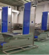
(II) Waterfall Type Cap Feeder (Model: SG-1200)
1. Brief Introduction
The waterfall type cap feeder is a new product developed on the basis of absorbing foreign similar products and combining the company's years of production experience. It is mainly used to transport bottle caps from a low position to the hopper of the capping machine at a higher position, serving as an auxiliary equipment for the capping machine. The equipment is driven by a crawler belt for transportation. It features stable operation, high production capacity and easy control, suitable for transporting plastic caps and aluminum caps.
2. Working Principle
When the photoelectric switch on the filling machine's hopper detects that the cap level is below the lower limit, cap feeding starts.When the photoelectric switch on the filling machine's hopper detects that the cap level is above the upper limit, cap feeding stops.As caps are gradually used and the level drops to the lower limit, step a is repeated. The cap feeder works reciprocally in this way.
(III) Cap Washing Tunnel
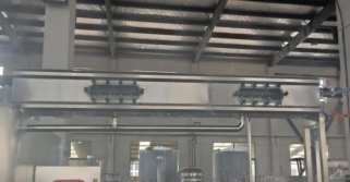
Reference Diagram of Cap Washing and Disinfection Tunnel
1. Product Brief Introduction
Caps are lifted by the conveyor to the cap sorter, sorted by the sorter and slid into the disinfectant spray guide rail. Disinfectant is pressurized by the pump and sprayed to all internal points of the caps through nozzles. Meanwhile, the caps are pushed forward by the water spray force. After disinfectant spraying, the caps enter the sterile compressed air spraying area to blow dry the disinfectant inside. Driven by the sterile compressed air spray force, the caps enter the sterile water spraying area, and then are sent to the closed guide rail by the sterile water spray force for transportation to the capping machine.
| 1 Set of Cap Disinfection System | Disinfectant Spray Guide Rail |
|---|---|
| Sterile Air Spray Guide Rail | |
| Sterile Water Spray Guide Rail | |
| Closed Guide Rail for Empty Cap Transportation | |
| Disinfectant Spray Pipeline (Including Pump and Disinfectant Storage Tank) | |
| Sterile Air Spray Pipeline | |
| Sterile Water Spray Pipeline (Including Pump and Sterile Water Storage Tank) | |
| Disinfectant Water Tank and Sterile Water Drainage Tank |
2. Product Features
(1) Empty caps are sprayed continuously online on the transportation and disinfection guide rails. The angle design of the nozzles ensures that the disinfectant is sprayed to all internal points of the caps, and the outer surface of the caps is sprayed and disinfected in the same way. Afterwards, the disinfected empty caps need to be rinsed with sterile water.(2) The empty cap transportation guide rail ensures the continuity of cap transportation, equipped with a 1-meter-long ultraviolet germicidal lamp with ultraviolet protection.(3) The disinfectant storage tank and sterile water storage tank can ensure the disinfectant dosage required for 2 hours of normal operation. The sterile water after empty cap spraying shall not flow into the disinfectant storage tank and shall be collected and discharged separately.(4) All components in contact with disinfectant shall be made of SUS316 material.(5) The cap feeding system is linked with the capping machine.
3. Technical Parameters
| Production Capacity | 2000 pieces/hour (standard plastic caps) |
|---|---|
| Applicable Cap Shape | Plastic threaded caps; Diameter Φ55mm; Height 16~24mm |
| Equipment Power | Cap sorting motor 0.18KW; Sterile water pump 0.75KW |
| Sterile Compressed Air Spraying Time | ≥10S |
| Corresponding Spraying Track Length | ≥2M |
| Sterile Water Spraying Time | ≥5S |
| Corresponding Spraying Track Length | ≥1M |
| Sterile Air Consumption | 0.4m³/min |
| Overall Dimensions | 300×300×1800mm |
(IV) LED Light Inspection (Model: LED-72W)
1. Introduction
The LED light inspection box adopts LED light source and imported high-light-transmission light guide plate, featuring uniform light intensity distribution, no dark areas, no flicker and stable color temperature, making the screen brighter and softer. It can be widely used in food, medical, electronic and other fields, and is particularly effective for inspecting chromaticity, turbidity, water leakage, visible substances and other defects.